
Industry news


View: 229

Release time:2026-05-25
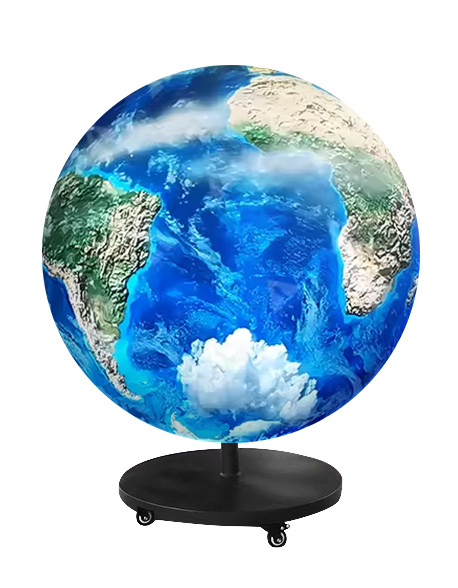
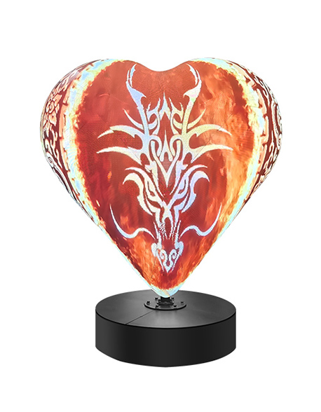
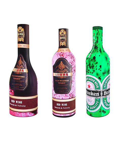
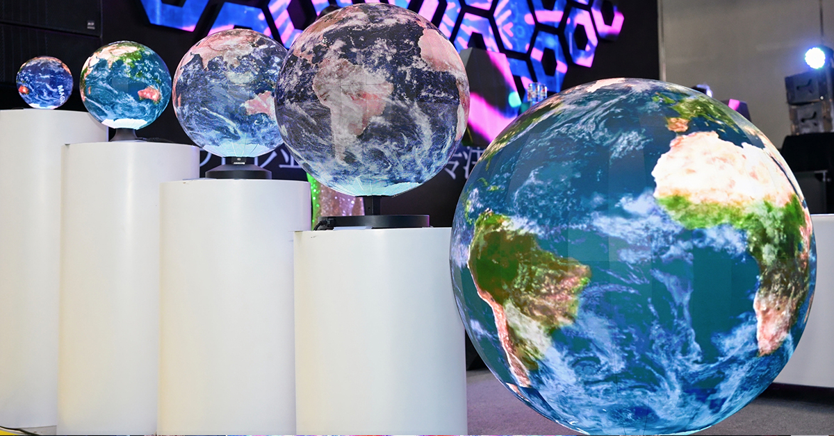
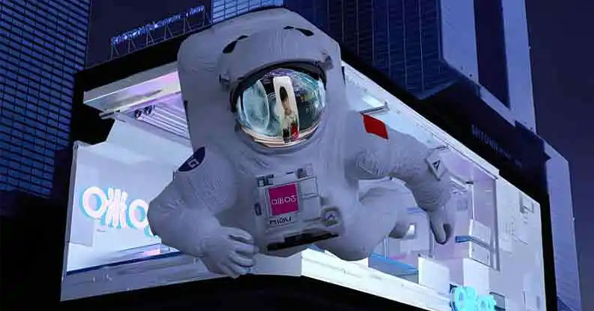
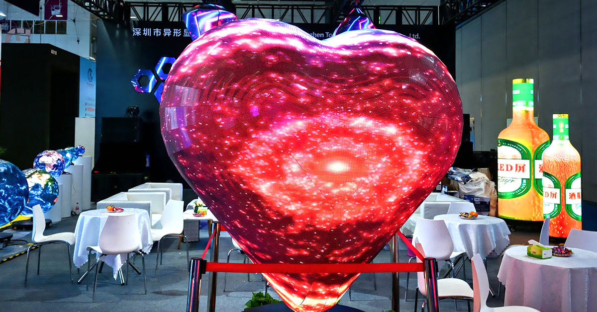
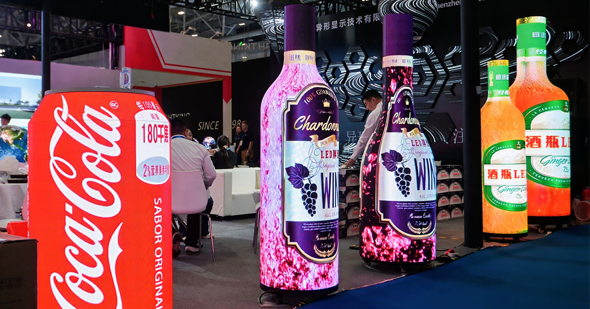
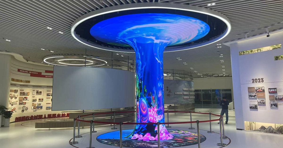
Irregular LED screens create immersive visual experiences that traditional flat displays cannot match. From spherical LED displays and curved video walls to LED tunnels and cylindrical screens, these custom installations attract attention in retail, entertainment, exhibitions, museums, and architectural projects.
However, many integrators discover a major challenge after installation: image mapping and signal configuration become far more complicated than on standard LED screens.
If cabinet rotation, receiving card parameters, or pixel mapping are configured incorrectly, the screen may show shifted rows, broken images, stretched content, or synchronization problems. These issues are especially common in custom-shaped LED projects.
This article explains why irregular LED displays are more likely to experience mapping errors and how engineers can avoid them during installation and system setup.
Standard LED screens usually follow a simple structure:
All cabinets face the same direction
Modules share identical resolutions
Data flows in a consistent pattern
Cabinet mapping remains linear
Irregular LED displays work differently. Their structure often includes:
Rotated cabinets
Curved surfaces
Non-standard module sizes
Mixed installation angles
Custom signal routing
As a result, the control system becomes significantly more complex.
One of the most common issues occurs when rows or sections shift horizontally or vertically.
This usually happens because:
Receiving card width and height are incorrect
Cabinet rotation settings are wrong
Data flow direction does not match the physical installation
Mapping parameters were not updated after rotating modules
For example, when installers rotate LED cabinets from vertical to horizontal orientation, they must also modify the receiving card resolution inside software such as:
NovaLCT
Colorlight LEDVision
Brompton Tessera
VX Series processors
Otherwise, the processor sends image data in the wrong direction, which creates visible row offsets across the screen.
Unlike flat LED walls, irregular LED displays rarely maintain a uniform cabinet orientation.
For example:
Spherical LED screens may use different module directions between the upper and lower hemispheres
Curved LED walls often require angled cabinet installation
Folded corner displays may combine multiple facing directions
LED tunnels frequently involve ceiling and sidewall rotation
Each directional change affects:
Pixel mapping
Signal routing
Scan direction
Receiving card configuration
If the engineer forgets to update rotation settings, the display may show mirrored images, tearing, or disconnected visuals.
Traditional LED cabinets usually follow common resolutions such as:
192×192
256×256
320×160
Irregular LED displays often use custom module dimensions instead.
Examples include:
Triangular LED modules
Trapezoidal cabinets
Narrow strip modules
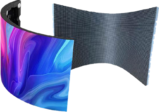
Curved flexible panels
These custom resolutions require more precise receiving card settings.
Even a small mistake in cabinet width or height can cause:
Misaligned content
Pixel overlap
Missing image sections
Distorted visuals
Therefore, engineers must verify every module resolution before loading configuration files.
Flat LED walls display content directly. Curved and cylindrical screens work differently because the processor must remap flat video content onto a curved surface.
This process often includes:
UV mapping
Pixel remapping
Content warping
Real-time scaling
If the mapping chain is incorrect, users may notice:
Broken seams
Uneven stretching
Image jumping
Visible transition lines
Cylindrical LED displays commonly experience seam alignment problems where the beginning and ending edges fail to connect perfectly.
Irregular LED projects usually involve more complex data routing than standard screens.
Installers often use:
S-shaped wiring
Loop routing
Multi-direction signal chains
Cross-connected receiving cards
As the system grows larger, troubleshooting also becomes harder.
If one HUB board or signal chain uses the wrong direction setting, the display may show:
Half-screen disorder
Interlaced shifting
Localized image offsets
Random flashing sections
Because of this, engineers should document the signal path before installation begins.

Common problems include:
Latitude seam misalignment
Upper and lower hemisphere reversal
Pole-area image stretching
Typical issues include:
Unclosed image seams
Left-right image breaks
Distorted panoramic content
Frequent problems include:
Ceiling and wall synchronization delays
Incorrect scan direction
Uneven brightness transitions
Common challenges include:
Broken corner visuals
Inconsistent scaling
Misaligned content at angles
Before installation, engineers should define:
Cabinet positions
Signal direction
Receiving card numbering
Network cable routing
This step greatly reduces troubleshooting time later.
Installers should clearly identify:
Which cabinets rotate
Which modules mirror
Which sections invert
Then they should configure these settings directly inside the control software.
Spherical, cylindrical, and tunnel displays require specialized content formatting.
Therefore, designers should prepare expanded video layouts before loading media onto the processor.
Always double-check:
Width and height
Scan mode
RGB order
HUB configuration
Data group assignment
Even a single incorrect parameter can affect the entire screen.
Irregular LED displays deliver stunning visual impact, but they also introduce more technical complexity than traditional flat screens.
Because these systems involve cabinet rotation, custom resolutions, curved surfaces, and advanced mapping, they face a much higher risk of display errors.
Fortunately, most problems can be avoided through proper planning, accurate receiving card configuration, and careful signal mapping.
When engineers combine strong installation practices with correct software setup, irregular LED screens can achieve seamless and highly immersive visual performance.
 +86 18688923792
  andy@tosled.com