


Industry news


View: 263

Release time:2026-05-14
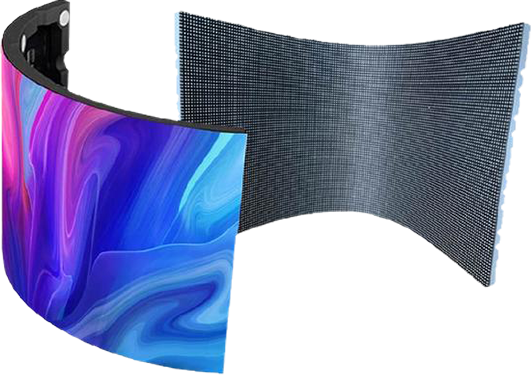
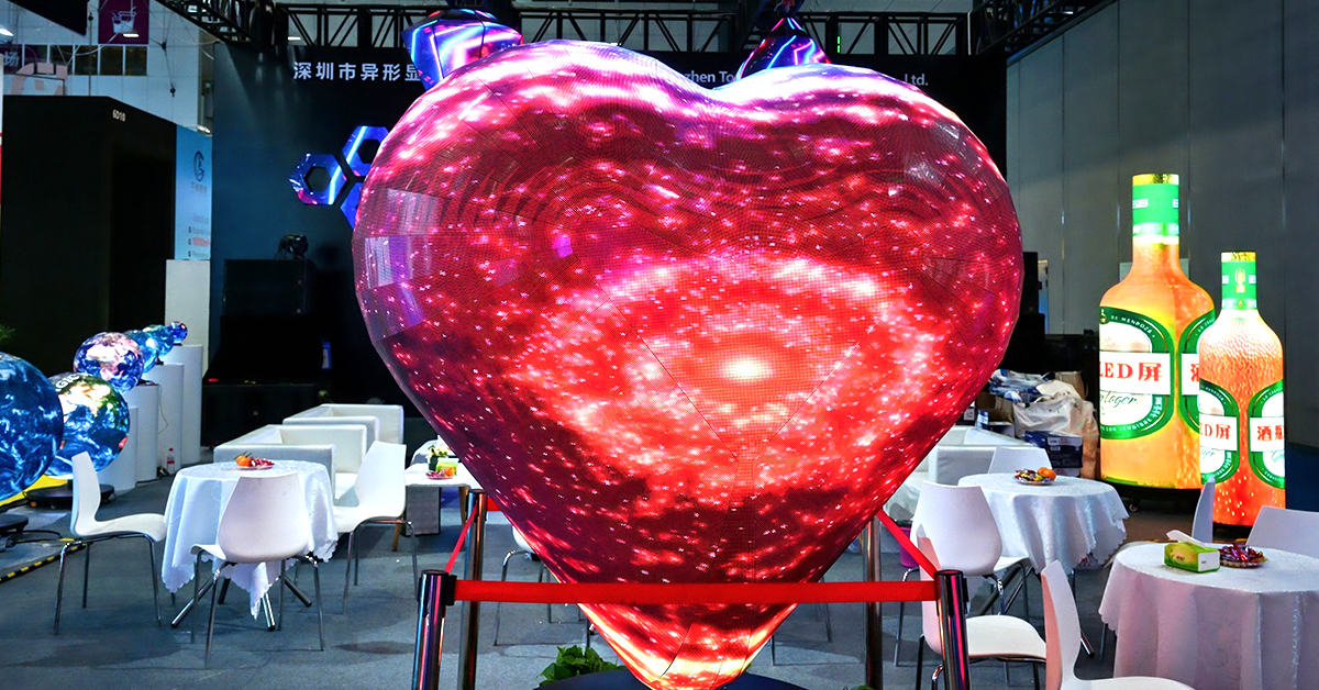
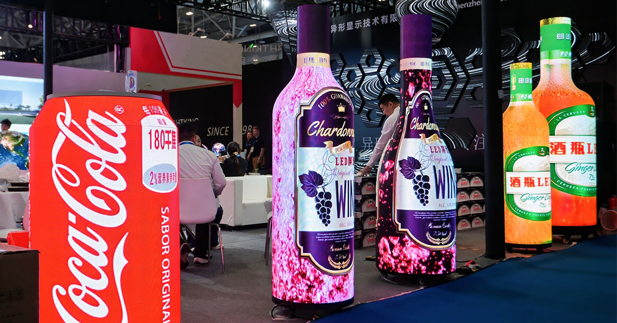
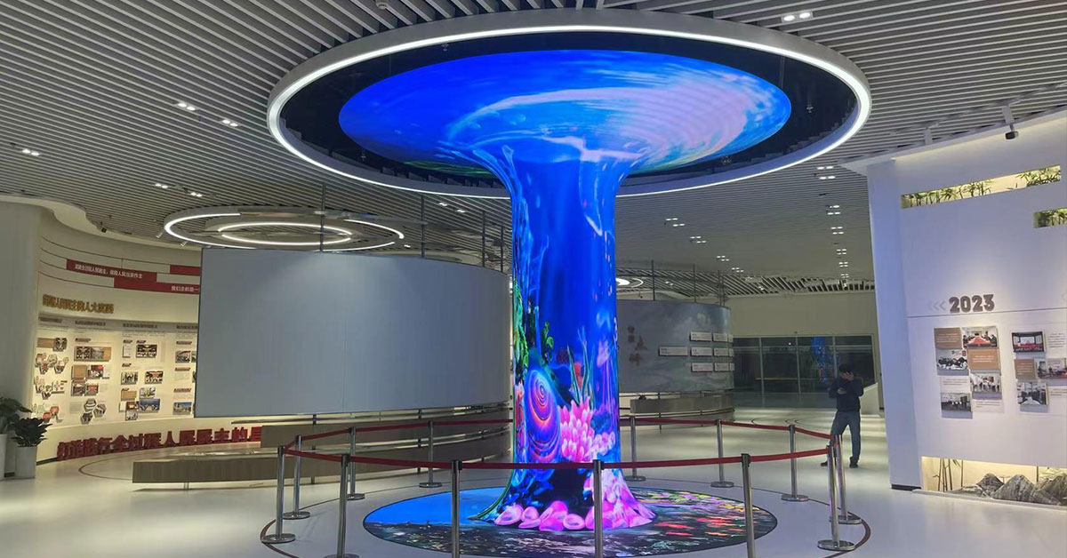
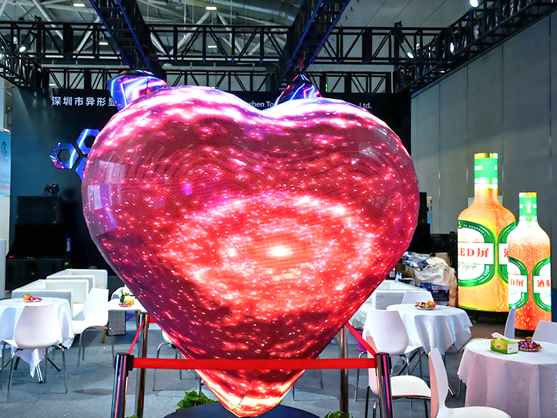
Irregular LED displays—such as cylindrical screens, spherical structures, wave-shaped ceilings, and freeform media façades—are not just a design challenge. They are fundamentally an engineering problem of how discrete LED modules approximate continuous curved geometry.
At the center of this system is one key enabler:
small-format LED modules
The smaller the module, the more geometrically flexible the entire system becomes. Everything else—structure, calibration, and content correction—builds on that foundation.
Irregular LED displays are not truly “flexible surfaces.” They are assembled from rigid units that approximate curvature through segmentation.
This leads to a simple rule:
Larger modules → coarse segmentation → visible edges, limited curvature
Smaller modules → fine segmentation → smoother geometry, higher curvature fidelity
In practical engineering terms, small modules enable:
tighter curvature radii (typically R ≥ 300 mm and above)
smoother transitions on cylindrical and spherical surfaces
reduced visual discontinuity between panels
These two parameters are tightly coupled:
Smaller pixel pitch (P1.2, P0.9, etc.) improves image detail
Smaller module size preserves geometric flexibility
Without both working together, you either get:
a sharp image that cannot curve properly, or
a curved structure with visible segmentation artifacts
Once module size is optimized, the next challenge is structural adaptation.
Irregular LED systems rely on cabinet designs that behave like mechanical joints, not rigid blocks.
Common engineering approaches include:
hinge-based locking systems for angular adjustment
“fishbone” support frames for distributed flexibility
sliding rail mechanisms for fine alignment
These structures allow the screen to conform to different spatial geometries without forcing stress into the LED modules themselves.
To maintain safety and stability in real installations:
cabinet size is usually kept ≤ 500 mm
single cabinet weight is typically ≤ 20 kg
This improves:
aerial installation safety
maintenance efficiency
long-term structural reliability
Once modules are arranged into a curved or irregular surface, the pixel grid is no longer rectangular. This introduces:
geometric distortion
stretching near edges
visual discontinuities between modules
To solve this, systems rely on nonlinear pixel mapping (Warped Mapping).
Engineers build a full 3D model of the installation and then generate:
pixel lookup tables (LUTs)
geometric transformation matrices
real-time correction shaders (OpenGL / GPU-based rendering)
This allows the system to:
pre-warp content before display
compensate for curvature distortion
maintain visual continuity across seams
In effect, the screen becomes a “mapped surface” rather than a flat display.
A typical high-end example is an 8-meter spherical LED installation built for immersive environments.
full spherical curvature alignment
weight reduction for suspended structure
seamless 360° viewing
serviceability from within or rear access
~270 hexagonal modules (around 160 mm each)
carbon-fiber lightweight frame structure
seam control below 0.3 mm
front-maintenance modular design
full spherical LUT-based image correction
The system achieves:
seamless 360° visual continuity
no visible black borders
stable brightness distribution across curvature
Real-world deployment is where most problems appear. The following issues are consistently underestimated.
Using too many non-standard modules increases:
cost dramatically
spare parts complexity
long-term maintenance risk
Best practice: use standardized modules wherever possible.
Curved structures naturally expand and contract under temperature changes.
If not properly designed:
panels may bulge
seams may misalign
stress accumulates over time
Solution:
always include expansion gaps (“breathing space”) in structural design
Dense modular systems can suffer from:
signal noise
synchronization issues
electromagnetic interference
Proper shielding and grounding design are essential from the early engineering stage.
Skipping simulation is one of the most expensive mistakes.
Without a pre-built digital twin:
installation errors go undetected until on-site assembly
calibration becomes significantly harder
rework costs increase sharply
Modern projects should always simulate:
structure
wiring
viewing angles
content mapping
before physical deployment.
At a system level, irregular LED engineering is not about making screens “flexible.”
It is about combining four tightly coupled layers:
Small modules approximate curved surfaces.
Flexible cabinet systems maintain structural adaptability.
Nonlinear mapping corrects geometric distortion.
Media is designed for the target spatial environment.
The success of an irregular LED display project does not depend on any single technology.
It depends on whether all four layers are properly aligned.
Small LED modules are the foundation—but only when they are integrated with structural design, calibration algorithms, and content adaptation does a truly stable irregular LED system emerge.
In other words:
Irregular LED displays are not built—they are engineered as a coordinated system of geometry, mechanics, and computation.
 +86 18688923792
  andy@tosled.com