


Industry news


View: 211

Release time:2026-05-12
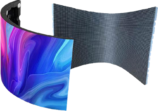
Custom-shaped LED displays create immersive visual effects, but they also introduce complex mapping and synchronization challenges. If the image shifts, stretches, overlaps, or displays in the wrong position, the issue usually comes from incorrect coordinate mapping, cabinet configuration, or sending card settings. This guide explains how to solve image offset problems on irregular LED screens efficiently.
What Causes Image Offset on an Irregular LED Screen?
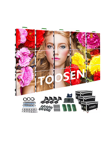
Unlike standard rectangular LED walls, irregular LED displays use non-linear cabinet arrangements. Therefore, the control system must remap video signals precisely. When the mapping data becomes inaccurate, the screen shows visible displacement.
Common causes include:
Incorrect receiving card coordinates
Wrong cabinet connection sequence
Resolution mismatch
Sending card configuration errors
Incorrect screen rotation settings
Faulty smart module data
Software mapping conflicts
Signal transmission instability
As a result, operators often notice:
Split images
Misaligned graphics
Cropped video content
Rotated display sections
Black gaps between modules
Step 1: Check the Physical Cabinet Connection
Before adjusting software settings, inspect the hardware structure carefully.
Verify Data Cable Direction
Many image offset problems happen because installers connect HUB boards or network cables in the wrong sequence.
You should:
Confirm the signal flow direction
Match the actual wiring with the software topology
Inspect every cabinet connection
Replace damaged Ethernet cables immediately
In cube screens, cylindrical LED displays, and curved installations, even one reversed cabinet can shift the entire image.
Step 2: Confirm Screen Resolution
Next, calculate the exact screen resolution.
For example:
Cabinet resolution: 128 × 128
Total cabinets: 10
Total screen resolution:
1280×1281280times1281280×128
If the video processor output resolution differs from the actual LED resolution, the screen will display image displacement or scaling distortion.
Therefore:
Match processor output resolution exactly
Avoid automatic scaling whenever possible
Use custom resolution settings for irregular layouts
Step 3: Rebuild the LED Screen Mapping
Most irregular LED screens require custom mapping.
Common Mapping Methods
1. Point-to-Point Mapping
The controller maps every pixel precisely to the physical LED position.
This method works best for:
Ribbon LED displays
Curved LED walls
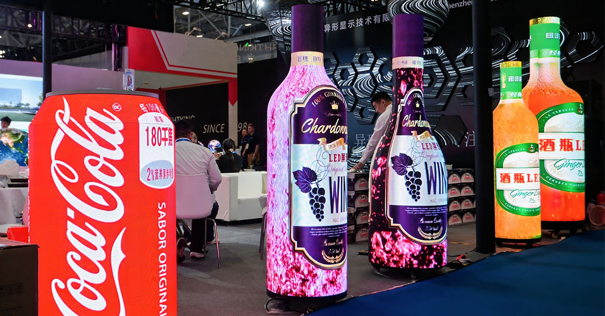
Creative retail LED installations
2. Cabinet Mapping
The system maps entire cabinets instead of individual pixels.
This approach:
Simplifies setup
Speeds up debugging
Reduces configuration time
However, it may reduce precision on highly irregular structures.
Step 4: Adjust Sending Card Settings
The sending card controls signal distribution across the entire display system.
You should verify:
Output resolution
Refresh rate
Scan mode
Data group assignment
Port loading limits
Many technicians solve offset issues simply by reloading the correct receiving card file.
Popular LED control systems include:
NovaStar
Colorlight
Linsn
Huidu
Brompton
Each platform uses different mapping logic, so always export and back up the configuration file before editing.
Step 5: Use 3D Coordinate Correction for Complex Shapes
Highly customized LED displays often require spatial correction.
For example:
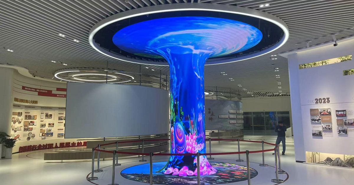
Cylindrical LED screens
Cube LED displays
Wave-shaped LED screens
Polygon LED structures
These projects usually need:
X/Y/Z coordinate mapping
Geometric correction
Perspective compensation
Edge blending adjustment
Otherwise, the content may appear stretched or shifted at viewing angles.
Best Practices to Prevent Future Offset Problems
To maintain stable display performance:
Label all cabinets clearly
Save backup configuration files
Use the same batch of receiving cards
Document signal routing diagrams
Calibrate after every structural adjustment
Test with grid patterns before final deployment
Additionally, keep firmware versions consistent across all controllers.
Conclusion
Image offset on a custom-shaped LED display usually comes from mapping errors, incorrect cabinet topology, or controller misconfiguration. Fortunately, you can solve most problems quickly by checking hardware connections, rebuilding mapping coordinates, and optimizing sending card parameters.
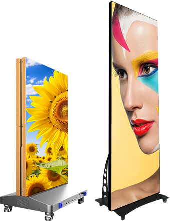
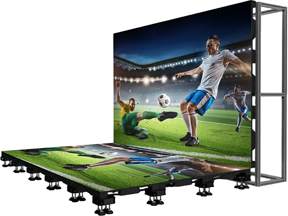
As irregular LED screens become more popular in retail, entertainment, and immersive digital art, accurate mapping and calibration will continue to play a critical role in display quality.
 +86 18688923792
  andy@tosled.com