

Industry news

View: 188

Release time:2026-05-12
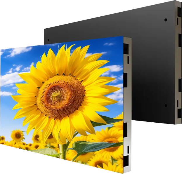
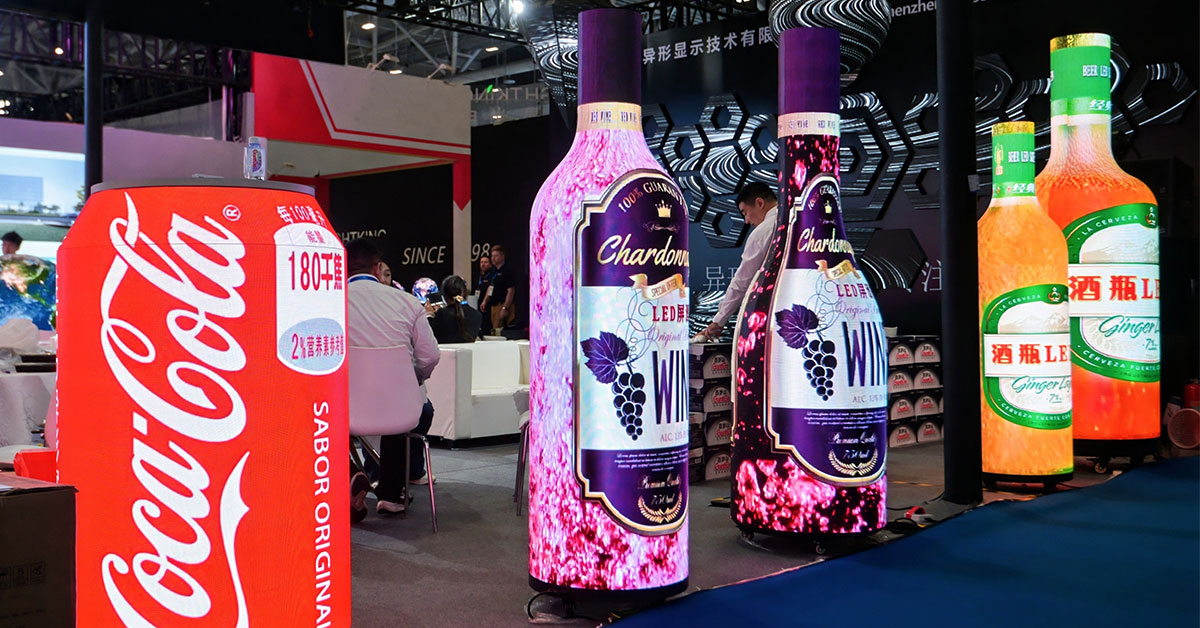
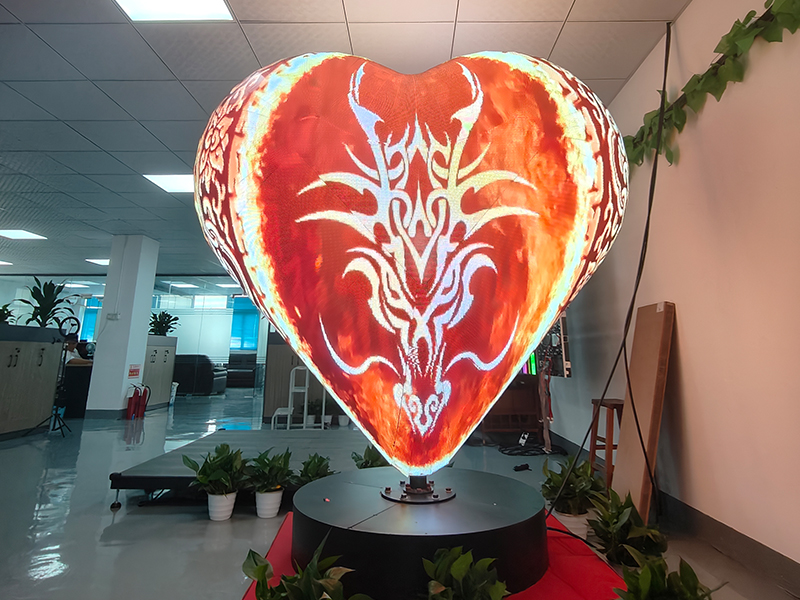
Custom-shaped LED displays transform ordinary digital signage into immersive visual installations. However, irregular structures also make configuration and debugging more complicated than traditional flat LED screens. This guide explains how professionals configure, test, and optimize creative LED displays efficiently.
Every irregular LED screen uses a unique physical layout. Therefore, technicians must analyze the structure carefully before they begin software setup.
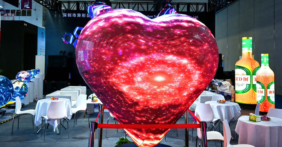
Common custom LED structures include:
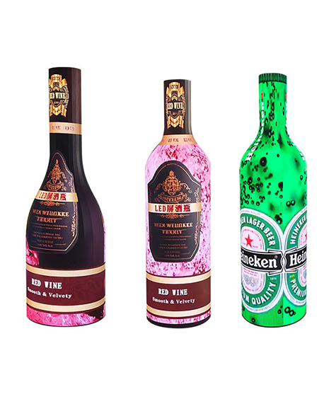
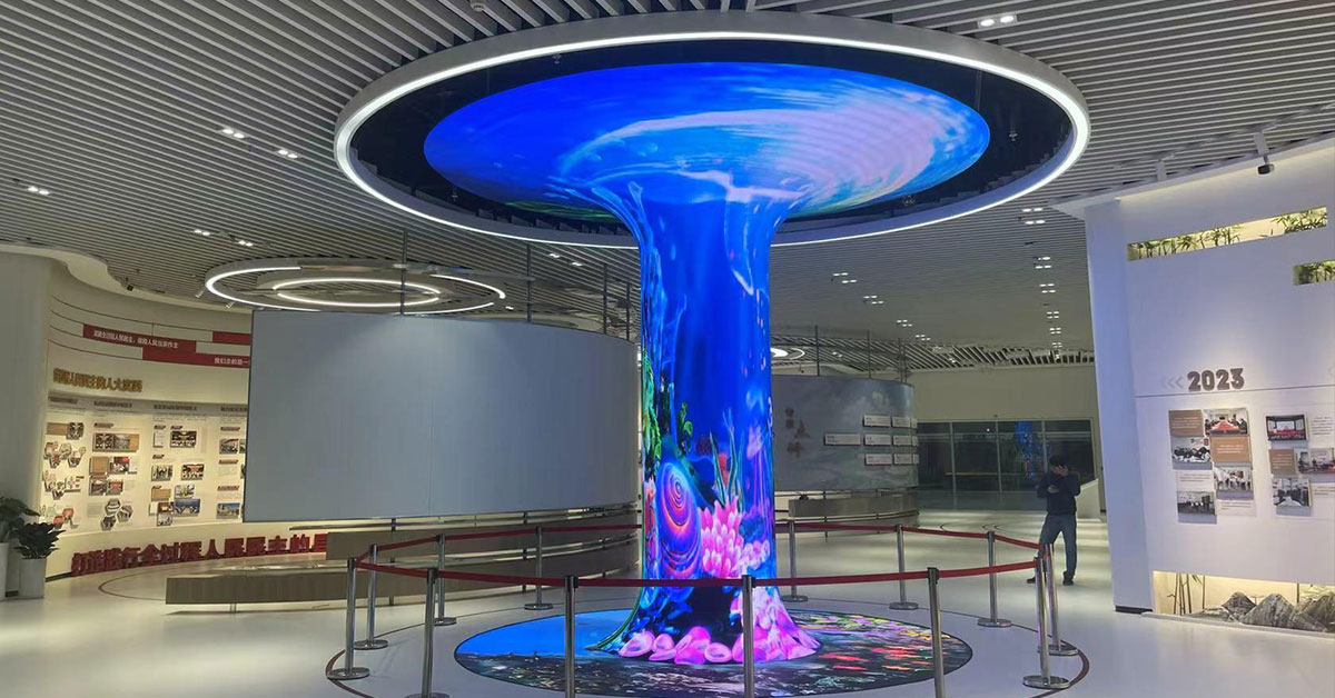
Cylindrical LED screens
Cube LED displays
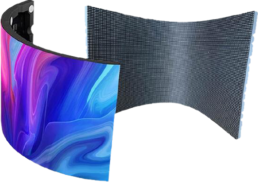
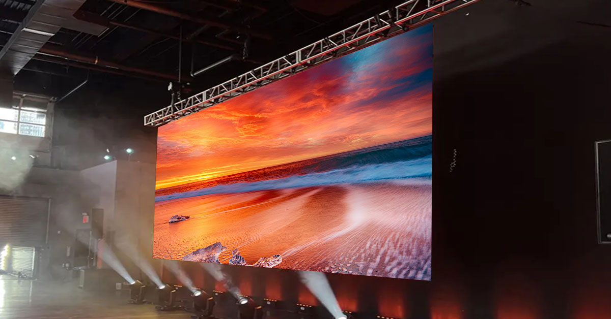
Curved LED walls
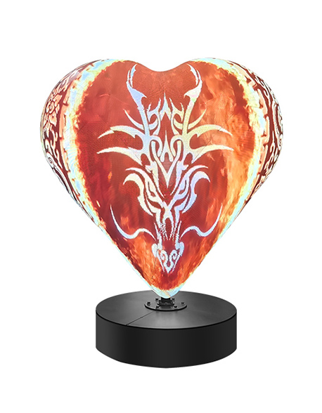
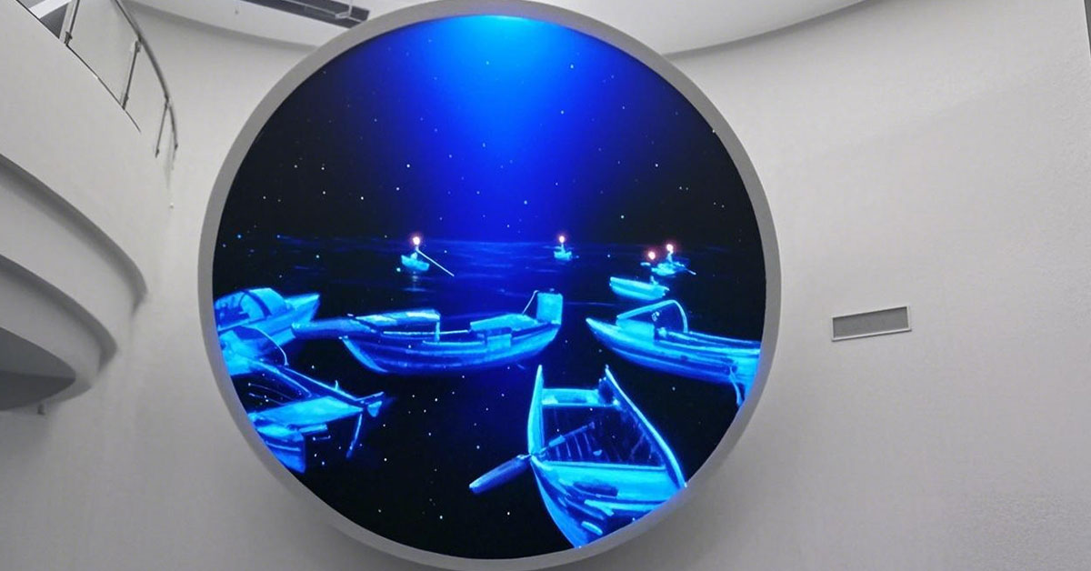
Spherical LED screens
Triangle LED modules
Wave-shaped LED installations
Because these displays break conventional cabinet alignment, accurate coordinate planning becomes essential.
First, determine the total pixel resolution.
Suppose:
One module resolution: 64 × 64
Total modules: 24
Then the full resolution becomes:
64×2464times2464×24
After calculation, configure the video processor and media server using the exact output resolution.
If the resolution does not match, the screen may show:
Black borders
Content compression
Signal overflow
Image displacement
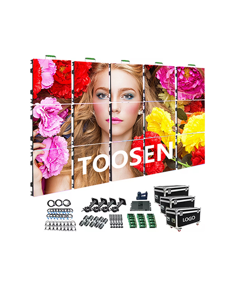
Receiving cards control data distribution inside the LED cabinets.
During setup:
Assign cabinet positions correctly
Match physical wiring order
Set module dimensions accurately
Define scan mode parameters
Load smart settings if available
Many debugging failures happen because technicians forget to synchronize cabinet order with software mapping.
Next, create the screen connection structure inside the control software.
Most LED software platforms provide topology tools that visualize:
Cabinet arrangement
Signal flow direction
Port loading
Data group allocation
For irregular screens, avoid automatic topology generation whenever possible. Manual mapping usually delivers better accuracy.
Step 4: Test the Screen Using Standard Patterns
Professional engineers always use test patterns before playing video content.
Recommended test patterns include:
Grid lines
RGB color bars
Grayscale gradients
Motion patterns
Checkerboard patterns
These patterns quickly reveal:
Dead pixels
Cabinet displacement
Incorrect rotation
Signal delay
Brightness inconsistency
Creative LED displays often distort images because of curved surfaces or unusual viewing angles.
To solve this problem, technicians use:
Geometric correction
Perspective mapping
Edge blending
Warp adjustment
3D spatial calibration
For example, cube LED screens require seamless edge synchronization. Otherwise, video content will break at cabinet intersections.
Step 6: Optimize Refresh Rate and Color Calibration
After completing structural debugging, optimize visual performance.
You should adjust:
Refresh rate
Gamma correction
White balance
Brightness uniformity
Color consistency
High-end applications such as XR virtual production and broadcast studios require especially precise calibration.
Problem | Possible Cause |
Image tearing | Incorrect refresh synchronization |
Screen flickering | Poor grounding or unstable power |
Partial black screen | Damaged receiving card |
Content misalignment | Wrong mapping coordinates |
Cabinet color difference | Calibration inconsistency |
Configuring a custom-shaped LED display requires both hardware expertise and advanced software mapping skills. Successful debugging depends on accurate topology planning, precise coordinate configuration, and systematic calibration.
As immersive visual technology expands across retail, exhibitions, entertainment, and architectural media, professional irregular LED debugging has become an essential capability in the LED display industry.
 +86 18688923792
  andy@tosled.com