


Industry news


View: 297

Release time:2026-04-10
Low-quality flexible LED screens often fail under repeated bending. As the material fatigues, electrical resistance increases, which leads to issues like dark lines, color shift, or partial dimming.
To improve bending durability, focus on three core principles:
use flexible materials, design a compliant structure, and keep stress away from critical circuits.
Material choice directly determines how well the display survives repeated deformation.
Material | Key Properties | Typical Use |
Polyimide (PI) | High temperature resistance and strong mechanical stability, but has a yellow tint | Traditional mainstream solution |
Colorless Polyimide (CPI) | optical transparency, can replace glass | Preferred for high-end flexible and foldable displays |
Ultra-Thin Glass (UTG) | Scratch-resistant and excellent barrier properties, but brittle | Often combined with CPI for hybrid structures |
PET / PEN | Low cost but limited heat resistance | Entry-level or temporary applications |
Key takeaway:
For high-performance flexible LED screens, CPI or CPI+UTG composites are becoming the standard.
Good layout design minimizes mechanical stress on conductive paths.
Align traces with the bending direction
Route circuits parallel to the bend whenever possible. This reduces tensile stress.
Avoid sharp angles in traces
Use large-radius curves instead of 90° corners to prevent stress concentration.
Add tear-resistant features
Reinforce edges with ribs, tabs, or buffer cutouts. This prevents edge cracking under load.
Reduce rigid component size
Use ultra-thin, miniaturized ICs and passive components. The fewer rigid parts, the better the flexibility.
Optimize LED layout
Avoid overly dense pixel arrangements in high-strain zones. Keep critical circuits away from bending hotspots.
Solder joints are one of the most failure-prone areas under repeated bending.
Apply underfill reinforcement
Encapsulate solder joints with underfill to improve mechanical stability and prevent cracking.
Optimize pad geometry
Use oval or elongated pads instead of sharp-edged shapes to reduce stress concentration.
Use thinner copper and pads
Thinner conductive layers deform more easily and are less likely to fracture during bending.
Even a well-designed screen can fail if installed incorrectly.
Respect the minimum bending radius
Static bending: typically ≥ R10 mm
Dynamic repeated bending: ≥ R20–R30 mm
Increasing the radius significantly extends lifespan.
Avoid reverse bending
Repeated back-and-forth folding (“kneading”) is a primary failure mode.
Always maintain single-direction bending when possible.
Add cushioning at stress points
Use foam or silicone pads at mounting points to prevent localized pressure damage.
Avoid tensile stress
Flexible LED modules are designed to bend, not stretch. Even slight stretching can damage circuits.
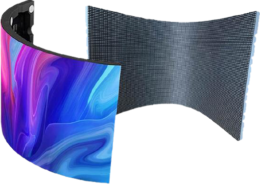
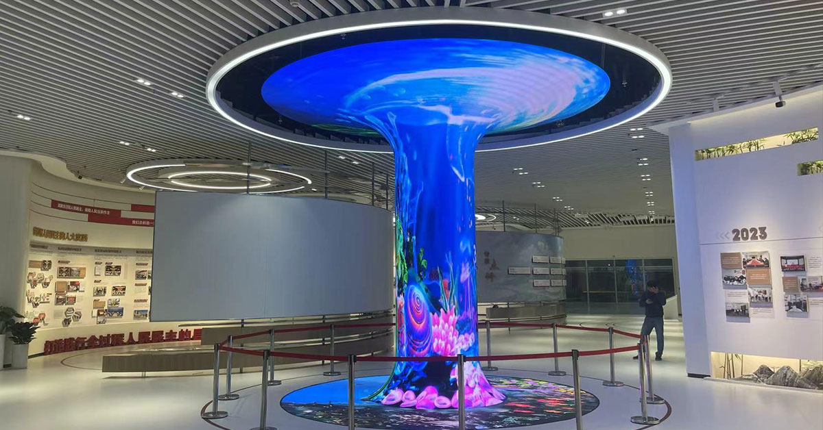
For demanding use cases like wave screens, rollable displays, or wearable installations, standard designs are not enough.
Segmented flexible architecture
Separate rigid zones (components) from flexible zones (bending areas).
Use serpentine or stretchable traces
These allow controlled deformation without breaking electrical continuity.
Apply protective surface layers
TPU or silicone coatings improve durability and protect against mechanical wear.
Improving bending durability is not about a single upgrade—it’s a system-level optimization:
Materials define the baseline flexibility
Structural design controls stress distribution
Installation determines real-world lifespan
If all four layers work together, a flexible LED display can handle thousands—even millions—of bending cycles without failure.
 +86 18688923792
  andy@tosled.com